Thanks for the picture. I did some research on the various forums last night to work out what's going on with this plumbing. So your catch tank is set up in series with the return to the manifold (no other changes)? This seems to be the most commonly used method.
Yes, sorry for my picture quality - no proper camera at the moment. I found this diagram which I have shamelessly borrowed

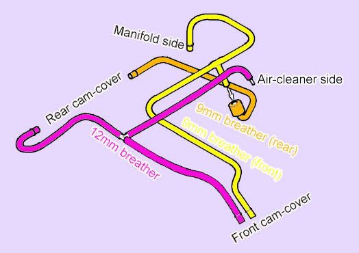
I gather in the original setup, the front and rear crank cases are breathing in from the air cleaner, and breathing out into the manifold.
Here is how my one is currently set up:
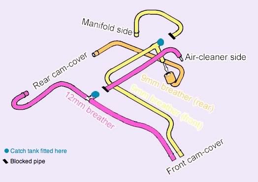
If I have that right, then the circuit is not breathing at all - it's just looping through the catch tank (breathing in and out through the catch tank breather pipe?). Stevez is suggesting there are different ways of plumbing it, but this one seems a bit odd to me?